Content
Rate Control Initialization (Stream Level)
Rate Control Start (Frame Level)
ABR Mode: I/P Frame Initial QP
Rate Control End (Frame-Level)
Rate Control Look Ahead Thread
Frame-Level Statistics in Look Ahead Thread
General
x265 RC (Rate Control) supports the following modes:
-
constant quantizer – specified by ‘–qp’
-
constant quality – default RC mode, specified by ‘–crf’
-
single pass ABR – to enable this mode non-zero bitrate should be specified in the command-line ‘–bitrate X’
-
forceQp – startFrameQp are fed from a qp-file (like in x264), specified by ‘–qpfile’
In constant Quality Mode (CRF) the x265 RC (Rate Control) attempts to keep near constant visual perception. For example RC will increase the QP for frames with significant motion (more coarse compression is compensated since HVS (Human Vision System) is less sensitive in high motions) and lower QP down for low motion. Notice that CRF mode in x265 is not complex. Frame start QP is specified by a predefined map taking the crf-value to QP (according to frame type). This mapping does not depend on video content at all.
Single Pass ABR : RC attempts to keep a predefined bitrate sometimes on account of visual quality degradation.
For both CRF and Single Pass ABR modes the adaptive quantization can be optionally turned on by setting ‘–aq-mode [1|2]’ in the command line. x265 supports two adaptive quantization modes (aq-modes): auto-variance (‘–aq-mode 2’) and aq_variance (‘–aq-mode 1’). In aq_variance (aq-mode=1) mode the aq-strength for all frames is the same, while in auto-variance mode (aq-mode=2) the x265 applies separate aq-strength for each frame, based on its energy (i.e. “complexity”) of current frame. In both modes the quantizer varies for each CTU, however the variability of the quantizer in the auto-variance mode is adaptive. For example if the picture consists off two stripes: the bottom is grass and top half is clear blue sky, then auto-variance would provide a bigger difference between higher and lower quantizers than that with aq-mode=1.
The x265 enables to set initial QP for each frame manually (i.e. via a corresponding txt-file). The txt-file location is specified via command line parameter ‘-qpfile’. If the ‘-qpfile’ is not specified then the initial QP and frame type are specified automatically.
In this note we consider CRF and single pass ABR rate control modes (without VBV).
Note: In constant quantizer mode – QP for P-frame is specified, x265 uses fixed QP offsets between I, P and B-pictures : by default -3 and +2 for I and B-pictures, compared to P-pictures. The rationale behind: I-pictures are referenced more than P-pictures, which in turn are referenced more than B-pictures. The more a picture is referenced, the more its quality impacts on other pictures and thus of the whole GOP.
1.1 Selected x265 parameters
–no-amp : disable assymetric partitions (e.g. 32×8)
–no-rect : disable rectangle partitions Nx2N and 2NxN
–no-tskip : disable transform skip mode (if video content is not animation or screen content it’s worth to disable this mode)
-b : maximal number of B-frames
–b-adapt : adaptive B-frame scheduling, 0 – disabled.
-s : maximal CU-size
–-tu-intra-depth : maximal depth of transform tree rooted at intra-CU
–tu-inter-depth : maximal depth of transform tree rooted at inter-CU
–rd : R-D decision level
–subme : amount of subpel refinement to perform (0:least .. 7:most)
–max-merge : maximum number of merge candidates
–-me : motion search method dia (0), hex (1), …
–no-signhide : disable hiding of sign bits
–no-lft : disable deblocking (in case of significant motion the deblocking can be disabled)
–qcomp : quantizer curve compression. The rationale is to increase the QP in areas with high complexity (since the visual threshold to noise is raised in highly-detailed regions) and consequently decreasing quality. To lower the QP in low-complexity areas and consequently increasing quality (the visual threshold to noise is lowered).
–cutree, –no-cutree : enable/disable CTU-tree algorithm.
Note: What’s cutree method (this method was inherited from x264 and in x264 it’s called MB-tree)?
The idea of CTU-tree is as follows: a block is more important if it is referenced by many other blocks, i.e. has many ancestors in the graph (or in the tree). CTU-tree makes sense if lookahead is enabled, otherwise we can’t know how much a given block is referenced in next frames. Strongly referenced blocks are quantized finer. I don’t recommend to compare CTU tree on against off with PSNR, it’s better to use HVS-related metrics like VMAF.
1.2 Presets
ultrafast: -s 32 –b-adapt 0 -b 4 –tu-inter-depth=1 –tu-intra-depth=1 –rd 0 –subme=0 –max-merge=1 –me=0 –no-amp –no-rect –no-tskip –early-skip –no-lft –no-sao –no-signhide –no-weightp
superfast: -s 32 –b-adapt 0 -b 4 –tu-inter-depth=1 –tu-intra-depth=1 –rd 0 –subme=1 –max-merge=1 –me=1 –no-amp –no-rect –no-tskip –early-skip –no-signhide –no-weightp
veryfast: –b-adapt 0 -b 4 –tu-inter-depth=1 –tu-intra-depth=1 –rd 0 –subme=1 –me=1 –max-merge=2 –no-amp –no-rect –no-tskip –early-skip
faster: –b-adapt 0 -b 4 –tu-inter-depth=1 –tu-intra-depth=1 –rd 0 –subme=1 –me=1 –max-merge=2 –no-amp –no-rect –no-tskip –early-skip
fast: –tu-inter-depth=1 –tu-intra-depth=1 –rd 0 –subme=1 –me=1 –max-merge=2 –no-amp –no-rect –no-tskip
medium: –tu-inter-depth=1 –tu-intra-depth=1 –rd 2 –max-merge=3 –no-amp –no-rect –no-tskip
slow: –b-adapt 2 -b 4 –tu-inter-depth=1 –tu-intra-depth=1 –rd 2 –max-merge=3 –no-tskip
slower: –b-adapt 2 –rc-lookahead 20 -b 5 –tu-inter-depth=2 –tu-intra-depth=2 –rd 2 –max-merge=4 –no-tskip –ref 3
veryslow: –b-adapt 2 –rc-lookahead 30 -b 9 –max-merge=5 –ref 5
placebo: –b-adapt 2 -b 16 –max-merge=5 –ref 16 –merange 124 –rc-lookahead 60
1.3 x265 Parallelism
x265 supports two paralleling schemas: frame-level and WPP (or mb-level or ctu-level in my jargon). It’s worth mentioning that applying parallel coding might deteriorate coding efficiency (it’s reported that WPP deteriorates the coding efficiency by 1%). Tiling parallelism is not available since the tiles-mode is not supported by x265.
First thread starts the k-th frame, the second thread waits until a several ctu-rows of the k-th frame have been completed (reconstructed pixels are available). Then the second thread commences (k+1)-th frame, the restricted search area of k-th frame is already available.
To enable frame-level parallelism in x265 you need disable WPP (use ‘–no-wpp’) and apply ‘–frame-threads’ by setting ‘–frame-threads N’, where N is the number of threads (desirable set N equal to the number of cores).
Example of frame-level parallelism [2 concurrently encoded frames]:
x265 –input a.yuv –input-res 3840×1744 –fps 24 –b-adapt 0 -b 0 –ref 1 –frame-threads 2 –no-wpp –rc-lookahead 2 -o test.h265
CTU-level parallelism is realized by means of built-in HEVC tool called WPP (Wavefront Processing). To enable the ctu-level parallelism with N threads you need disable the frame-level multi-threading (by setting ‘–frame-threads 1’) and enable the wpp mode and set the number of threads (–threads N).
Example of ctu-level parallelism with 3 threads
x265 –input a.yuv –input-res 3840×1744 –fps 24 –b-adapt 0 -b 0 –ref 1 –threads 3 –frame-threads 1 –wpp –rc-lookahead 2 -o test1.h265
Rate Control: Coding Thread
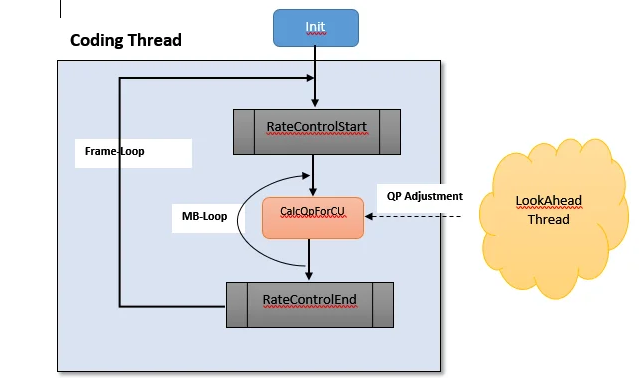
x265 consists of two main threads: coding thread and look-ahead (preprocessing) thread, notice that the look-ahead thread keeps ‘–rc-lookahead’ frames ahead the coding thread (adding latency). The look-ahead thread gathers frame statistics and builds QP-adjustment map for RC (if adaptive quantization is on), decides on P/B frame type decision etc.
In the coding thread Rate Control consists of two levels: MB-level (or CTU-level) and frame-level:

2.1 Rate Control Initialization (Stream Level)
RateControl constructor is invoked once, at the beginning of coding. This function performs the global resources and parameters initialization:
-
Specify the scaled picture size (for lookahead): scaled[W|H]
-
In case of CRF the particular constant parameter RateFactor is specified as follows (by the hard-coded formula taken from the thin air):

where ‘crf’ is a number in command line (followed by ‘–crf’)
-
Rate Control Parameters Init
-
VBV Init
2.2 Rate Control Start (Frame Level)
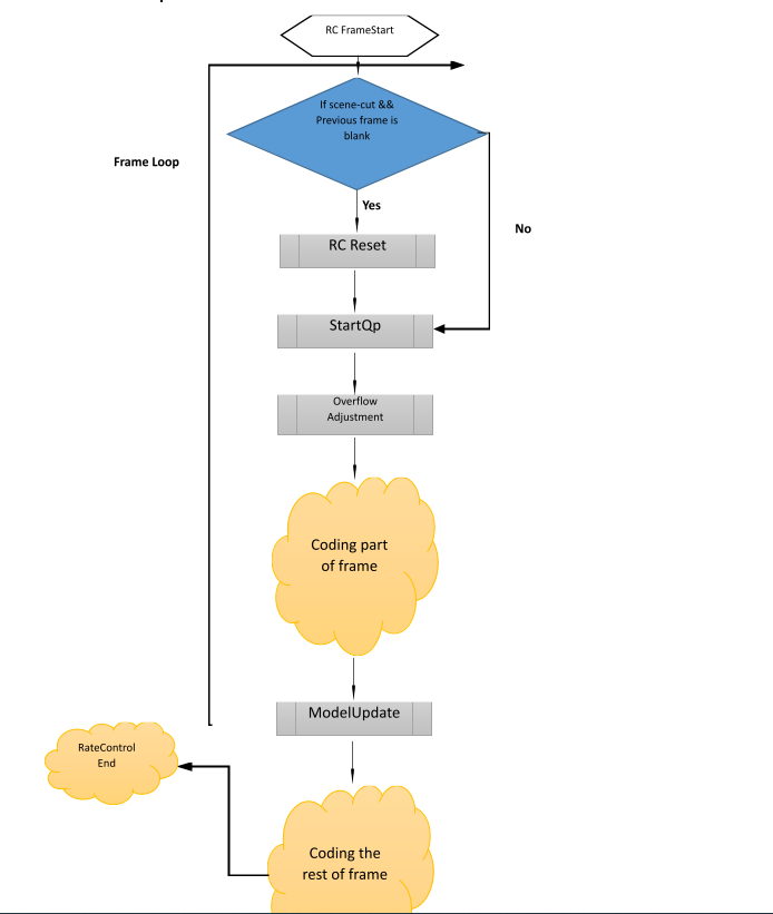
The function RateControlStart is invoked once per frame and consists of three functional blocks:
-
Check RC Reset Conditions
-
FrameStartQp – compute the start QP unless qpfile mode is on
-
Overflow Correction
-
ModelUpdate – update of RC model parameters

RC is reset if a scene cut is detected between the current and previous frames (since it’s expected that current Rate Control model is no longer relevant for the new scene).
Scene-cut condition:current_frame_average_satdCost > 4 * moving_average_satdCosts
FrameStartQP
This module FrameStartQP is tailored to calculate the start or initial QP for a current frame which would have produced the desired bit-size if it had been applied to all frames from the stream start or the last Rate Control reset.
The R-D curve (or Bits to Qscale curve) is approximated by qscale = X/Bits, where ‘X’ is the complexity of the frame (the complexity is Rate Control model parameter, adaptive). For I/P frames we firstly determine qscale = X/Bits and then convert qscale to QP units, it’s worth reminding that QP is not a scale factor, it’s rather an index in a corresponding look-up table:
startQP = 12.0 + 6.0*log2(qscale/0.85)
B-Frame Initial QP
In case of B-frames for both CRF and ABR modes the initial QP is obtained by blending of avgQPs of forward and backward references (weighted by POC differences) + m_pbOffset, where m_pbOffset is determined as follows:
m_pbOffset = 6.0 * LOG2(pbratio)
If the B frame is used for reference (B-pyramid mode) then
m_pbOffset = m_pbOffset/2
pbratio is specified by the command-line parameter ‘–pbratio’
ABR Mode: I/P Frame Initial QP
For I/P frames the qscale is firstly specified:
qscale = C * X / m_wantedBitsWindow
- X – the model parameter updated each frame.
- C – constant specified as (0.04*fps)^0.4 , more magic number pulled out thin air.
- m_wantedBitsWindow – the desired bit-size equal bitrate*frameDuration*FramesCoded since the start of the stream or the last RC reset.
Upon computing of qscale, the clipping to the range [lqmin, lqmax] is performed, where
lqmin = lastQscaleOfPFrame / 2^(2/3)
lqmax = lastQscaleOfPFrame * 2^(2/3)
The clipped qscale is assigned to lastQscaleOfPFrame to be used in the next P-frame.
For I/P frames the initial qscale is computed constantly as follows:
qscale = (0.04*fps)^0.4 / RateFactor
Then qscale is converted to start QP:
startQP = 12.0 + 6.0*log2(qscale/0.85)
If the previous I-frame bits have been completely amortized (i.e. !m_partialResidualFrames ) then startFrameQp is adjusted according to overflow conditions:
timeDone = framesDone *m_frameDuration
wantedBits = timeDone * bitrate
if (wantedBits > 0 && m_totalBits > 0 && !m_partialResidualFrames)
{
abrBuffer *= MAX(1, sqrt(timeDone));
overflow = Clip3(.5, 2.0, 1.0 + (m_totalBits – wantedBits) / abrBuffer);
startFrameQp *= overflow;
}
RC model parameter complexity X is updated once per frame but not at start of frame. At the initial period (equal to ‘2*frame_rate’ frames) RC model is updated at the middle of each frame (actually at the start of ‘(m_numRows + 1) / 2’ row). After the initial period finished the RC is modified after ‘m_refLagRows’ completed. Notice m_refLagRows takes usually small magnitudes (since search area vertical size is usually several CTUs), i.e. RC is updated after several ctu rows (almost at the start) of each frame.
m_refLagRows = 1 + (search_range + 63) / 64
In case of frame-based parallelism – do not allow the next frame to enter rateControlStart until this frame has updated its mid-frame model parameter.
2.3 CalcQp per CU
QP-adj map is specified in the Look-ahead thread for each 32×32 block (in the original resolution). However, QP-delta is signaled per 64×64 block. Therefore the average of four QP-adjustments (comprising the current 64×64 CTU) serves as QP-adjustment of the current CTU.
2.4 Rate Control End (Frame-Level)
At the end of each frame the function rateControlEnd is called. This function performs the following operations:
-
Update/Compute statistics
-
Amortization of I-frame
The following statistics are updated/computed:
-
The average Qp (after HVS QP-adjustment), stored in m_avgQpAq
-
Update m_wantedBitsWindowby bitrate*frameDuration
-
Update accumulated complexity m_cplxrSumby ‘bits*avgQp’
-
Update m_totalBits
To prevent from RC to make “panic” decision due to I-frame peaks, x265 cheats RC – instead of providing the actual I-frame bit-size to RC, the reduced (faked) I-frame bit-size is fed and not-declared “hidden” bits are amortized among the following inter frames.
At the start of each I-frame the number of amortizing frames is determined:
m_residualFrames = min(75, keyframeMax)
Then the delta in bits (m_residualCost) to be added to each amortizing frame is specified:
m_residualCost = (int)((bits *0.85) / m_residualFrames) // 85% of i-frame size is not declared!!!
Then the actual bit-size (bits) is reduced:
bits -= m_residualCost * m_residualFrames
In other words the hidden size is m_residualCost * m_residualFrames and the faked bit-size (bits) is fed to RC.
At the start of non-I frame the hidden bits are added if m_residualFrames!=0
bits + = m_residualCost
m_residualFrames -= 1
Rate Control Look Ahead Thread
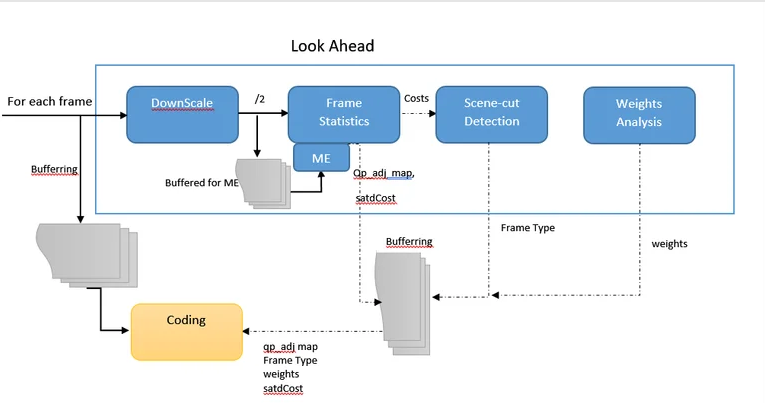
Look-ahead consists off the following main stages applied to each frame prior to the coding:
-
Downscale the frame (by the factor two). There are many techniques to scale images, most popular are Nearest Neighbor,
Bilinear, Bicubic, Spline, and Lanczos. The Nearest Neighbor considers the closest pixel, Bilinear – the closest 2×2 pixels, Bicubic
the closest 4 × 4 pixels. Spline and Lanczos consider more surrounding pixels.
-
Compute frame statistics (total satdCost etc.) on scaled frames.
-
Determine qp_offset
-
Scene-cut Detection on scaled frames for adaptive I-frame placement
-
Weights Analysis on scaled frames if the weighted prediction (–weightp ) enabled
The look-ahead process is performed in a separate thread in reverse-scan order within a frame (unlike to coding).
Frame-Level Statistics in Look Ahead Thread
Remind that frames in the look-ahead are scaled down. Each scaled frame is divided into 16×16 blocks.
4.1 CTU Cost (SATD-based)
For each 16×16 scaled block (CU) the residual cost is computed and stored at lowresCosts array.
The following operations (for each lowres CU) are executed to compute lowresCost:
-
[Inter-Cost] Perform motion estimation with the search area 16×16 on previous scaled frame and return ‘mcost’, where mcost= SATD + λ*R(MV)
-
[Intra-Cost] For all 35 intra modes, select the smallest SATD cost – ‘icost’
-
Disfavor intra-cost: icost = icost + 9
-
Store icost in intraCost array
-
3. lowresCost = mcost
4. [Decision] if icost<mcost then lowresCost = icost and m_intraMBs++
5. lowresCosts[cu_num] = lowrescost
Notes:
-
At the stage (2) the best intra mode is ignored (because we are in look-ahead thread), only minimal cost is exploited.
-
In order to exploit MV prediction (remind that MV is also estimated) the 16×16 blocks are traversed in reverse order (from right to left, from bottom to top).
-
In addition to lowrescost,icost and m_intraMbs are further used.
4.2 QP-adj Map
For each 16×16 scaled block qp_adj (or qp_offset) is determined basing on the block ‘energy’. The sum of 16×16 luma and two 8×8 chroma variances is called ‘block energy’. The energy is computed by the utility ‘acEnergyCu(pic, block_x, block_y)’.
qp_adj formula:
qp_adj = (energy+1)^0.1
The qp-adjustment is stored in the buffer qpCuTreeOffset to be used lately (during encoding).
Notes:
-
qp_adj is monotonically increasing function of the energy, the more energy the coarser quantization.
-
Because qp_deltasignaling granularity is 64×64 and qp_adj is specified for each 32×32 block (in the original resolution), the average of qp_offsetsof all 32×32 blocks comprising a given 64×64 CTU is taken as the final qp-adjustment for the 64×64 CTU.
4.3 Frame-Level
For each frame two costs are calculated: icost (sum of intra costs) and pcost (sum of inter residuals). These costs are further used in scene-cut detection.
Scene Detection
The purpose of scene-cut detection – adaptive placement of I-frames if the new scene is detected.
Scene detection is performed on the sliding window of successive frames. The size of the window equals to look-ahead depth, by default the look-ahead depth is 20 frames.
5.1 Flashlights Detection
To minimize false detection rate, the scene detection mechanism contains a sort of flashlights discernment: if the previous scene-cut has been recognized (num_bframes+1) frames ago then the current scene detection is flashlight and false alarm.
However, flashlight-detection is applied only in case num_bframes>0. So, for IP-only streams flashlights might cause false scene-cut detections and as a result plenty irrelevant I-frame placements. It’s worth to modify this code.

5.2 Scene-cut Detection Bias
In the command line the scene-cut detection can be disabled by ‘–no-scenecut’ or ‘–scenecut 0’, by default scenecut enabled.
According to the position of current frame in GOP (curGopPos), the bias is determined as follows:
threshMax = scenecutThreshold / 100.0
threshMin = threshMax * 0.25 /* magic numbers pulled out of thin air */
if ( keyframeMin == keyframeMax )
threshMin = threshMax
if ( curGopPos <= keyframeMin / 4)
bias = threshMin / 4
else if (curGopPos <= keyframeMin)
bias = threshMin * curGopPos / keyframeMin
else
{
bias = threshMin + (threshMax – threshMin)*( curGopPos – keyframeMin) / (keyframeMax – keyframeMin)
}
Here
-
scenecutThreshold – specified in the command line ‘–scenecut X’, default 40
-
keyframeMin – specified by ‘–min-keyint’ in the command line and denotes the minimal GOP size (relevant if I-frame placement at scene-cuts enabled).
-
keyframeMax – specified by –keyint, equal to GOP size.
Let’s consider the common case when GOP size (GopSize) is fixed, i.e. keyframeMin = keyframeMax .
if the current frame is at the first quarter of GOP then
bias= threshMax/4
else
bias = threshMax * curGopPos / GopSize
Note:
The bias for frames in the first quarter of GOP is less than that in the rest of GOP.
5.3 Scene-cut Detection Mechanism
To detect scene-cut icost (sum of intra costs) and pcost (sum of inter residuals) are compared as follows:
If pcost/icost >= 1.0 – bias then
Scene-cut detected
Note: The maximal magnitude of the bias depending on scenecutThreshold – the greater scenecutThreshold the greater bias . Hence, the fewer pcost/icost ratio is required to declare scene-cut.

23+ years’ programming and theoretical experience in the computer science fields such as video compression, media streaming and artificial intelligence (co-author of several papers and patents).
the author is looking for new job, my resume


